Wall mount humidity sensors for building automation system (BAS) applications are produced and sold by several different companies and have a  reputation of poor accuracy despite specifications from suppliers. There is a rational reason why these instruments appear to read outside of their stated accuracy, which in turn causes users to be frustrated with the results.
Most wall mount units for BAS applications are multi-variable instruments and often measure temperature and/or CO2 level in addition to relative humidity. The output signals are also more complex and may include BACnet and Modbus® communication protocols in addition to analog current and voltage outputs. Optional LCD displays for local indication of measurements are also commonly found in these devices. All electronic components included provide the parameter measurement, output, and display, which create additional heat inside the wall mount housing where the humidity sensor is located.
Since relative humidity is the ratio of the partial pressure of water in the air divided by the saturation pressure of water in the air (of which the latter is a function of temperature), relative humidity is inversely proportional to the local temperature. This means that as the temperature inside of the wall mount housing increases relative to the room temperature, the internal humidity sensor will read lower values compared to the actual room humidity found in a stagnant airflow environment, such as an office. The stagnant airflow here is key. Humidity calibration chambers always have moving air systems to maintain uniform humidity throughout the chamber, so they do not reflect the stagnant environments that the wall mount sensors will later be expected to measure. When the wall mount units are returned to the manufacturer due to poor accuracy, they are inserted into a humidity chamber where the moving air ventilates the heat out of the wall mount housing. The humidity sensors are calibrated without the internal heat seen in a real world office environment. The wall mount sensors are then sent back to the customer who finds the units are still reading low when installed.
Dwyer engineers discovered this calibration conflict and devised the following solution which has been incorporated and is currently standard in the latest North American and European housing design options of the Series CDTA and CDTR wall mount products, shown to the right.
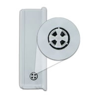
Solution: A separate temperature sensor is mounted on the outside of the wall 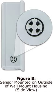 mount housing and thermally isolated from the internal housing wall (see figure B, left).
The internal humidity temperature sensor inside the housing is carefully calibrated to the outside temperature sensor so that minor variations in temperature between the inside and the outside of the housing can be determined. The saturation pressure of water is a well-known, complex function of only temperature. The humidity and temperature inside the wall mount housing is measured, and is always higher than the temperature outside of the housing. The difference of these two temperatures is used to compensate the humidity so that it indicates an accurate humidity measurement for the room.
There are several other factors required to make this work in the real world, 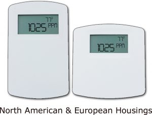 but this is the fundamental principle of the Digital Intelligent Temperature Compensation Algorithm (DITCA™) in the new carbon dioxide family of product lines now available for sale exclusively through Dwyer Instruments.
Note: Details of the Active Humidity Compensation are U.S. Patent Pending by Dwyer Instruments.