Proving Flow Through Chillers
Water chillers are nothing new with nearly an estimated 100,000 units operating in North America alone. Chillers are the cooling machines of choice to condition industrial, commercial, and institutional facilities. They are used to lower the temperatures of all kinds of equipment and processes such as: robotic machinery; semiconductors; injection and blow molding machines; welding equipment; die-casting and machine tooling; paper and cement processing; power supplies; power generation stations; compressed air and gas cooling systems; medical imaging machines; chemical, drug, food and beverage production; even simply to cool potable water to desirable levels. Whether for office comfort, keeping data server centers from overheating, or specialized industrial processes, water temperature control plays a vital role in many of the behind-the-scenes activities that affect our everyday lives.
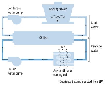
For those without the background or experience of dealing with a chiller, they consist of a reservoir that is filled with a fluid. A water or an ethylene glycol/water mix is continually circulated. In a typical building application they circulate chilled water to air-handlers or use chilled beams in order to transfer heat from air to water; or stated another way, transfer cooling from the water to the building air.
There are two primary chiller types: absorption and refrigerant. The two possess a significantly different cooling process. Absorption chillers use a heat source such as natural gas or steam to create a refrigeration cycle. Refrigerant chillers use mechanical compression and are the most common. Refrigerant compression chillers consist of four main components - a compressor, an evaporator, a condenser and a valve metering system. Basically, a refrigerant gathers heat, and then uses an evaporator heat exchanger to remove that heat. The evaporator expels the heat to the atmosphere, while the refrigerant is subsequently sent to a condenser where it converts back into a liquid and then is compressed. Finally, the refrigerant goes back to the heat source to start the process over.
There are two main styles of refrigerant compression chillers, air and water. Air condensers are cooled by utilizing the air, whereas water condensers are cooled by using water sources. Water cooled chillers are generally located within the building and use cooling towers, a pond, or river located near the building to reject water's heat from the condenser.
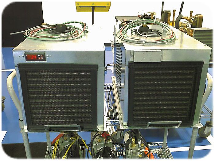
Chillers with condensers cooled by air operate essentially the same as those cooled by water regarding the refrigerant cycle and the steps along the way, xcept the cooling medium on the condenser is air instead of water. Air cooled chillers are intended for outdoor installation and operation. These reject heat to the atmosphere by mechanical means such as circulation of outdoor air by a fan directly through the machine's condenser. These types of condenser cooled units do not require a cooling tower as is common with water cooled chillers because the air rejects the heat directly to the atmosphere.
The main component that defines how the chiller will operate is the compression method of the refrigerant in its vapor phase. Four common styles exist: reciprocating compressors, centrifugal compressors, rotary screw compressors and rotary scroll compressors. Each have their key benefits for selection, such as: ideal operation zone to match the process's specified required cooling tonnage load, moving parts, noise, as well as the key component to throttle up or down to meet a demand shift.
Like a car's engine, reciprocating compressors possess a crankshaft and pistons. The pistons compress the gas; heating the gas. The hot gas is discharged to the condenser. The pistons have intake and exhaust valves that can be opened on demand to allow the pistons to idle. This gives an extra energy efficiency component since the capacity can be reduced as demand is reduced, thus making this type a good choice for buildings with a large swing in demand or long lengths of little demand. A few examples of this would be in an office or school, but not necessarily a hotel or an apartment building. Common capacities range from 20 to 125 tons but can even get up to 450 tons.
Centrifugal compressors operate much like a centrifugal water pump. They contain an impeller that compresses the refrigerant. Centrifugal chillers can provide a very high cooling capacity in a compact design. They have the ability to vary capacity continuously to match a wide range of load conditions with near proportional changes in power consumption; great for tight temperature control and energy conservation.This type can tackle the largest capacities and range from 150 tons up to 2400 tons.
Rotary screw or helical DNA type compressors have two mating helically grooved rotors. As the rotors rotate, the gas is compressed by volume reduction between the two rotors. These helixes require high tolerances to fit perfectly, thus driving up the initial cost. Capacity is controlled by a sliding inlet valve or variable-speed drive (VSD) on the motor. Capacities range from 25 to 450 tons with the largest capable of 800 tons.
Rotary scroll compressors use two spirals to pump and compress the refrigerant. Commonly, one of the scrolls is fixed while the other orbits eccentrically without rotating within the other fixed scroll. This motion traps and compresses pockets of fluid between the scrolls. This design and operation makes them the most efficient of the four compressor types. Single refrigerant loop scroll compressors range from 2 to 25 tons with the largest capable of 80 tons.
Typical chilled water cooling temperature ranges between 39-45 °F.
For proper heat transfer between the circulated water to be cooled and the refrigerant, it is important to maintain sufficient chiller water flow. The commonly recommended range of chilled water flow velocity is between 3 and 12 feet per second. Therefore, it is very important for a chiller to maintain this flow for proper efficiency and corresponding energy usage as well as maintaining long-term performance.
Numerous methods exist for the proving of flow through chillers. Each method offers certain advantages depending on the desired result.
Differential Pressure Measurement
Several instruments can be used to measure the differential pressure across a chiller. The differential pressure measured corresponds to the flow rate; the higher the flow, the higher the DP. Differential pressure switches or transmitters are most common.
Differential Pressure Switch
A differential switch may be installed across a chiller and the set point adjusted to switch at a certain differential pressure.
Advantages
• Adjustable set point
• No power required
• Low cost
• Simple operation
• No moving parts
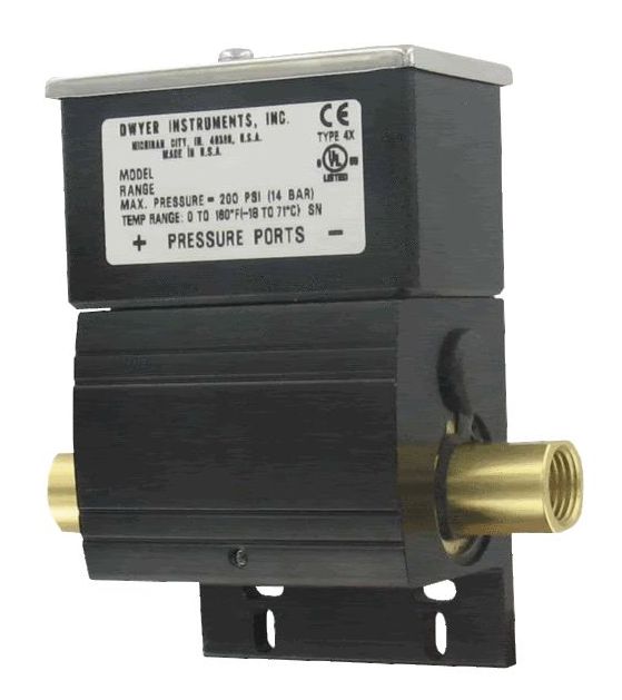
The Series DX Differential Pressure Switch is the perfect product for the job with adjustable set point down to 1 psid. The unit features a high static pressure rating of 200 psig (13.8 bar) for higher static pressure applications. Standard is a weatherproof, UL type 4X, enclosure for dust laden, outdoor, or wash-down installation environments. The DX uses opposing diaphragms to sense the high and low pressure with a pivot mechanism that transfers the difference of the two pressures to the SPDT switch.
Differential Pressure Transmitter
A differential transmitter may be installed across a chiller. These devices will require power and provide a 4-20 mA or 0-10 VDC output signal representing the actual differential pressure measured across the chiller. This signal can in turn be wired to a control system or to the building monitoring system.
Advantages
• Accurate measurement of flow
• Linear analog output for control or monitoring
• No moving parts
Some typical products include the following:
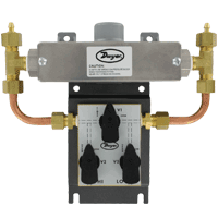
The Series 629C Wet/Wet Differential Pressure Transmitter monitors differential pressure of air and compatible gases and liquids. The design employs dual pressure sensors converting pressure changes into a standard 4 to 20 mA output signal or field selectable voltage. Small internal volume and minimum moving parts result in exceptional response and reliability. The terminal block, as well as a zero adjustment button are easily accessed under the top cover. The Series 629C Wet/Wet Differential Pressure Transmitter is designed to meet NEMA 4X (IP66) construction.
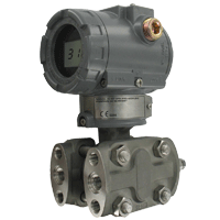
The Mercoid® Series 3100D Explosion-proof Differential Pressure Transmitter is a high accuracy (0.075% FS) microprocessor-based high performance transmitter, which has flexible pressure calibration, push button configuration, and programmable HART® Communication. The Series 3100D is capable of being configured for differential pressure applications. A field calibrator is not required for configuration.
Flow Measurement
These devices sense the flow rate. Flow switches or transmitters are available.
Vane Flow Switch
A vane flow switch may be installed in the pipe to prove flow. The size of the vane is cut or adjusted depending on the pipe size and the flow rate
expected and will switch at a certain flow.
Advantages
• Low cost
• Easy Installation
• Simple operation
Some typical products include the following:
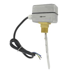
The Series FS-2 Vane Flow Switch offers an economical flow proving solution. Custom set points tailored for the application are enabled by field adjustable vane layers and a set point adjustment screw. The FS-2 features an aluminum weatherproof housing for indoor or outdoor installation. Paddles are adjustable to fit 1? to 8? size pipe. The FS-2 is ideal for use in "flow / no flow" applications.
Thermal Dispersion Flow Switch
A thermal dispersion flow switch may be installed in the pipe to proof flow. The impulse thermal dispersion measurement technique to measure the flow rate where the probe is heated above the process temperature and then is allowed to cool down to the process temperature
Advantages
• Easy Installation
• No moving parts
• Low pressure drop due to small insertion depth
• Simple operation
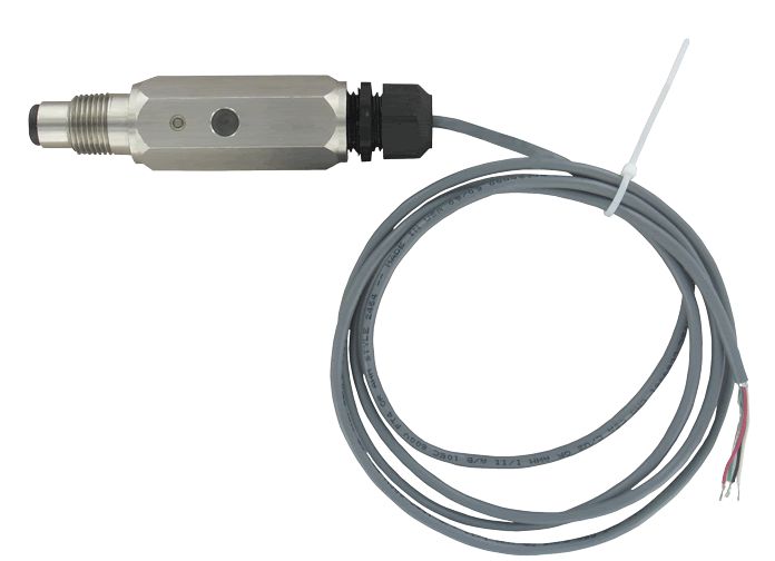
The Series TDFS is a thermal flow switch that indicates whether the flow rate is above or below a user set flow rate with NO and NC contacts. Set point is easily field set; just put the included magnet to the set point target at the desired flow rate and it's done. Incorporated into the unit are two LED status indicators on opposite sides of the unit providing visual switch indication, green when the flow is above set point, red when the flow is below set point.
What is a Calibrator and why is it an important device? Introduction to Instrument Calibration