Methods of Air Balancing
Air balancing a distribution system is needed to properly direct the air flow in order to optimize the system’s design. Flow rates are tested, adjusted, and balanced as cubic feet per minute (CFM) or cubic meters per hour (m3/h). There are two traditional methods for balancing airflow at the terminals. The first is sequential balancing, which involves setting the zone and branch dampers in sequence. However, the most common method of air balancing is called proportional balancing.
For traditional proportional balancing, an air flow hood, or capture hood, is the most popular test instrument used to take air flow readings. Traverse readings in the duct with a Pitot tube or a hot-wire thermo-anemometer is another accepted method of capturing the actual air flow.
Dwyer has designed a variation of proportional balancing, which is called Predictive Balancing used in Dwyer’s Series SAH SMART Air Hood® Balancing Instrument. Predictive Balancing is designed to be a faster process and give more accurate results than traditional proportional balancing.
Predictive vs. Proportional Balancing
In traditional proportional balancing, the flow hood will directly measure volumetric air flow at the outlets or terminals of a system: the registers, grilles, and diffusers. Most air flow hoods are cone shaped and aligned to the ceiling registers as shown in Figure 1 in the left picture. When a flow hood is placed over a terminal, it will generate pressure within the duct system, which reduces the air flow to the terminal. This condition is called back pressure. The effect of back pressure can result in errors when taking readings. Before using a flow hood, many technicians recommend performing a duct traverse to verify the K factor. Some digital flow hoods include back pressure compensation that attempts to calculate the effect of backpressure for the technician.
Dwyer’s Predictive Balancing technique is based on mass balance and energy conservation methods. Predictive Balancing, is a process that involves predicting the ideal flow set points for each TUA (Terminal Under Adjustment) so that every terminal is at the target flow until the process is complete. Dwyer’s Series SAH SMART Air Hood® Balancing Instrument was designed with Predictive Balancing in mind. Dwyer’s air hood is being used in Figure 1 in the right picture.
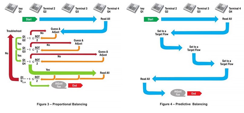
Predictive Balancing is deterministic and minimizes the number or process steps involved in testing, adjusting, and balancing HVAC systems. Figure 2 illustrates a comparison between Predictive Balancing and traditional proportional balancing processes, showing how much faster Predictive Balancing is.

Proportional Balancing
With proportional balancing (reference Figure 3), the technician balances a terminal proportional to the key terminal. To start a proportional balance of a system, one requirement is that the system has an 80% to 120% rate to the total design flow. Systems that are higher or lower than this range will not balance properly. If the system is outside of this range, the fan speed should be adjusted to get within range. Once set, the air flow from each terminal will remain the same ratio to other terminals.
If key Terminal 1 has a design flow percent of 60%, then Terminal 2 is 57%, Terminal 3 is 65%, and the ratio to the key Terminal 1 is 57% / 60% = 0.95. Meaning Terminal 2 will deliver 95% of the air volume of Terminal 1. With Terminal 1 as the key, delivering 100% of design flow, then Terminal 2 will be delivering 95% of the design flow. This will meet the design requirements. For example, if the damper for Terminal 3 is adjusted down to 525 CFM, the flow from Terminal 1 may increase to 550 CFM. In this case, Terminal 2 is within the design range; 550 * 0.95 = 523 CFM.
Once the terminals are in balance, with the proper ratio of tolerance with each other, they remain in balance with each other even though the air volume may change. All terminals in the system are then proportionally balanced. The fan RPM can be set to deliver the intended total air volume and all terminals will deliver the design flow within the established tolerances.
This process requires the balancing technician to adjust the flow from the terminal under-adjustment (TUA) to the key to gain the correct flow proportion. The key terminal’s flow changes when the TUA damper is changed. It may take several iterations to achieve the proper flow proportion.
Since the technician is estimating where to set the flow rate of the TUA relative to the key, the tolerance can vary considerably, which limits the accuracy of the balancing. The illustration in Figure 3 shows the potential number of lengthy steps involved with proportional balancing.
Predictive Balancing
The Predictive Balancing (reference Figure 4) process begins by opening the dampers to capture the total flow. The total flow is distributed into the four terminal flows. The terminal flows are determined by the terminal and damper loads and the pressure drop in the system.
Terminal 2 is the first damper adjusted in the system, and Terminal 1 is the key. Predictive Balancing calculates the ideal flow set point for Terminal 2 for TUA and predicts flows for Terminals 1, 3, and 4.
After adjusting the Terminal 2 flow to the ideal flow set point, Predictive Balancing calculates the ideal set point for Terminal 3 and predicts the new flows for terminals 1, 2, and 4.
To finish, Predictive Balancing calculates the ideal set point for the last Terminal, number 4, and flows for Terminals 1, 2, and 3 are correctly proportioned to the target.
Finally, Predictive Balancing calculates the ideal flow for Terminal 4 so the blower flow can be adjusted to bring all the terminal flows to the target flows.
Predictive Balancing also monitors and compensates for load on the blower/fan from the damper closures during the balancing process. The illustration in Figure 4 compared to Figure 3 shows just how much easier and faster Predictive Balancing is over Proportional Balancing in the amount of steps involved in the process.


