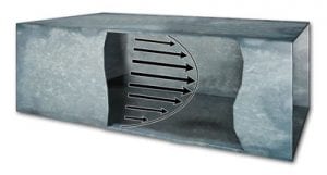
The velocity of an air stream in a duct is not uniform over the cross section of the duct. This is because friction against duct walls causes the air velocity to be lower near the sides than the velocity in the center, creating a parabolic velocity profile.
Fans, corners, duct fittings, tees, and coils all create turbulence in the duct, further changing the velocity over the cross section. Readings should always be taken with at least 8 and 1/2 duct diameters upstream and 1 and 1/2 duct diameters downstream from any device or intrusion that can cause turbulence.
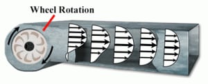
Based on these conditions, the air velocity must be averaged over the cross section of the duct to get an accurate measurement. To get an average air velocity, a formal pattern of sensing points is taken over the duct cross section. These are known as traverse readings. There are two main patterns for traverse readings: equal-area and log-linear.
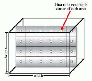
For rectangular ducts using the equal-area method, the cross section is divided into small rectangles of equal area. The velocity is taken at the center point of each of these rectangles and then averaged to get the duct velocity.
Using this method, the minimum amount of reading points taken is 16 and the maximum is 64. If less than 64 reading points are being taken, the distance between the points should not be more than 6 inches. In the example shown, 4 holes are drilled into the duct wall and the Pitot tube or anemometer is inserted into each hole to take four readings traversing the duct width or height. The reading points are the center of each of the rectangles.
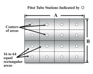
Rectangular Equal Area Method
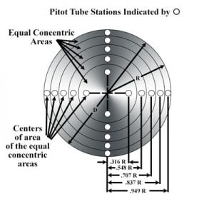
For round ducts using the equal-area method, the velocity pressure should be taken at the center of equal concentric areas and averaged. In the example shown, two holes are drilled in the centerline of the duct. One set of reading points is taken vertically and a second set is taken horizontally.
If the duct diameter is greater than 14 inches, then use 20 reading points; if it is between 10 and 14 inches in diameter, use 16 reading points; and if it is less than 10 inches in diameter, use 10 reading points with half the points in each reading plain. The reading plains do not have to be vertical and horizontal, but they do need to be 90 degrees from each other. Use the formulas shown for the insertion depth of each reading according to the duct radius.
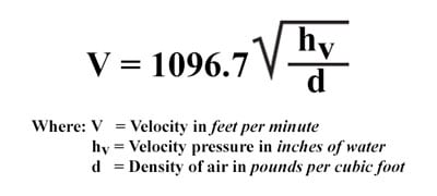
If using a Pitot tube, the velocity is directly proportional to the velocity pressure and can be calculated using the formula shown for air with V (velocity), d (density of air in the application), and hv (the velocity pressure from the measuring device).
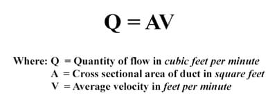
From the velocity, it is easy to calculate volume flow rate where flow rate Q is equal to the velocity multiplied by the cross sectional area of the duct or pipe.
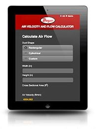
Dwyer Instruments, Inc. has an Air Velocity and Flow Calculator on the website. It is also downloadable as a mobile application for iOS® and Android® devices. This calculator will take velocity pressure to calculate velocity and calculate air volume flow rate with the cross-sectional area. It also offers the ability to make air density corrections for humidity levels.
For more detailed information, please check American Society of Heating, Refrigerating and Air-Conditioning Engineers (ASHREA), National Environmental Balancing Bureau (NEBB), Air Movement and Control Association International (AMCA) standards, or National Balancing Council (NBC).
