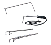
Dwyer offers many styles of Pitot tubes. Pitot tubes are commonly used sensors for monitoring air velocity and flow rate in heating, ventilation, and air conditioning. Some examples include the: Stainless Steel Pitot Tube Series 160, Telescoping Stainless Steel Pitot Tube Series 166T, and “S” Type Stainless Steel Pitot Tube Series 160S.

Pitot tubes are based on Bernoulli’s equation, which states that an increase in the speed of a fluid occurs simultaneously with an increase in dynamic pressure and a decrease in static pressure. Pitot tubes sense the dynamic pressure of the fluid flow at a particular point and were invented by French Engineer Henri Pitot in the early 18th century.
A Pitot tube consists of two tubes in one probe that sense both total and static pressure. The flow impacts on one tube, pointing directly into the fluid flow, that senses the total pressure in the duct or pipe. Radial holes perpendicular to the flow sense the static pressure in the duct. The space between the inner and outer tubes permits transfer of sensed pressures to the pressure connections on the opposite of the Pitot tube.
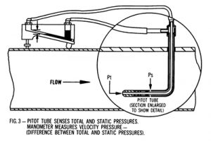
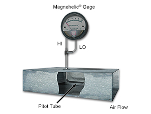
The pressure connections of the Pitot tube are then connected to a differential pressure instrument, such as a manometer or Magnehelic® Differential Pressure Gage. The pressure reading shown by the instrument is the velocity or dynamic pressure, which is the difference of the total pressure (on the high pressure port) and the static pressure (on the low pressure port).
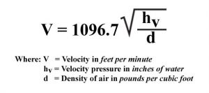
The fluid velocity is directly proportional to the velocity pressure and can be calculated using the formula V = 1096.7 √hv/d for air, with V the velocity, d the density of air in the application, and hv the velocity pressure from the measuring device.
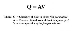
From the velocity calculation, volume flow rate can be determined using the formula Q=AV. Flow rate Q is equal to the velocity multiplied with the cross sectional area of the duct or pipe.
Dwyer also has an Air Velocity and Flow Calculator on our website and downloadable as a mobile application for Android® devices. This calculator converts pressure to air velocity. Using the cross sectional area, it calculates air volume flow rate. The calculator also offers the ability to make air density corrections for humidity levels.
If manual corrections are not desired, Dwyer offers instruments that can read directly in velocity or volume flow rate, such as the Magnehelic® Differential Pressure Gage, Magnesense® II Differential Pressure Transmitter, or Digihelic® Differential Pressure Controller.