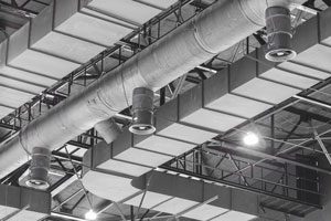
 High duct-static pressure creates problems during a building fire when fire dampers close. Closed fire dampers cause downstream duct sensors to detect a drop in pressure. The duct pressure sensors in turn send signals to crank the air handler even faster to get back up to normal operation. Because the fire dampers are closed, when the air handler ramps up, the duct pressure upstream of the fire dampers will increase to a point where a high static pressure switch will cut power to the VFD (variable frequency drive) and send a signal to the DDC (direct digital control). Switches in this application — by specification — are all manual reset and require two outputs: one for cutting power to the VFD and one for sending the signal to the DDC.
Traditionally, there have been three tactics to address this issue, each with its own problems.
Traditional Tactics & Problems
Tactic — An SPDT (single-pole, double-throw) differential pressure switch with manual reset and separate powered relay
Problem — Two devices have to be installed, mounted and independently wired. In addition, a separate power loop is required for the relay and is often missed or improperly powered upon installation. The extra wiring and installation add time and cost.
Tactic — A DPDT (double-pole, double-throw) differential pressure switch with manual reset and required external power
Problem — The second relay inside actually requires power. In this case, the installation is no different than using an SPDT switch with manual reset and separate powered relay, except the relay is mounted internally to the switch. So you eliminate having to mount a separate external device, but you still have the issues and costs associated with installing a power loop to the device.
Tactic — A differential pressure switch with manual reset and two internal SPDT contacts
Problem — The switches will activate on the pressure increase in the system the fire dampers have caused, but will not activate simultaneously. Therefore, the lag time of the two signals poses a problem. If the fan receives a signal first to shut down, the coinciding pressure drops. This prevents the second, independent SPDT switch from activating and notifying the DDC. Users would never receive a signal notifying them that an error had occurred.
The ideal solution would be a DPDT manual reset switch that doesn’t require power and features outputs that react simultaneously.
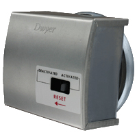
Eliminate common problems of high duct-static cutout applications with the Series 1831.

The Series 1831 DPDT low differential pressure switch features:
- Both contacts activate and reset simultaneously
- Power not required to operate
- Dual conduit openings for each control loop
- Bracket included for quick mounting
The Dwyer Series 1831 DPDT Low Differential Pressure Switch with manual reset requires no power and activates both outputs at the same time, making it the ideal solution for high duct-static cutout applications.
Since the 1831 doesn’t require power to drive its outputs, you don’t need a separate power loop and associated wiring and conduit, reducing material and labor installation costs. Both control contacts activate at the same time. The potential of the lead switch shutting down the fan, thereby preventing the lag switch from sending an alarming signal to the DDC, is no longer a probable system liability. Potential costly maintenance calls are reduced. Unlike typical switches with only a single conduit entry for both control loops, the Series 1831 provides two conduit connections, simplifying wiring while eliminating additional conduit tees.
The adjustment is easy to access for the set point, which can span across two available ranges: a 2.5″ to 9″ w.c. model or a 7.5″ to 23″ w.c. model. With its power-free operation and simultaneous output, the Series 1831 has become the superior choice for high duct-static cutout applications.
If you have any questions, the Dwyer Applications Engineers are available to assist by phone at (219) 879-8868 x6402, or by email at tech@dwyermail.com.
