So you’ve decided to track how much energy your HVAC system consumes in order to increase the system’s energy efficiency — great! But how will you do it? There are multiple methods that can be used to measure thermal energy in hydronic systems. We’ve outlined several methods below to make it easier for you to select the best technology for your application.
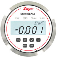
![]() Measuring thermal energy requires three components: a fluid flow sensor, two temperature sensors (one for inlet temperature, one for outlet temperature), and a calculator. Although thermal energy can technically be measured without a calculator, doing an energy calculation by hand is very complex and can introduce manual calculation error into the measurement. For that reason, we recommend incorporating a calculator into your system for the most accurate energy measurements. This calculator can be either an independent BTU controller, part of your building management system, or integral to a complete thermal energy system. A complete system includes a flowmeter, temperature sensors, and a calculator that are all calibrated together, eliminating the need for multiple pieces of equipment. Continue reading “Measuring Thermal Energy in Hydronic Systems”
Measuring thermal energy requires three components: a fluid flow sensor, two temperature sensors (one for inlet temperature, one for outlet temperature), and a calculator. Although thermal energy can technically be measured without a calculator, doing an energy calculation by hand is very complex and can introduce manual calculation error into the measurement. For that reason, we recommend incorporating a calculator into your system for the most accurate energy measurements. This calculator can be either an independent BTU controller, part of your building management system, or integral to a complete thermal energy system. A complete system includes a flowmeter, temperature sensors, and a calculator that are all calibrated together, eliminating the need for multiple pieces of equipment. Continue reading “Measuring Thermal Energy in Hydronic Systems”


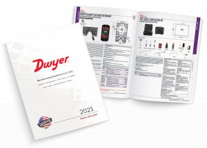 In this age of virtual meetings and online connections, to “Google” something has become synonymous with quickly looking up information. For some, bookshelves are more for decor than they are functional, and trends are leading to becoming more environmentally-friendly and saving paper. Print media is not necessarily “dead,” but it is becoming much less prevalent as we journey forward in this digital age.
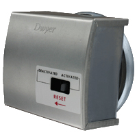
 High duct-static pressure creates problems during a building fire when fire dampers close. Closed fire dampers cause downstream duct sensors to detect a drop in pressure. The duct pressure sensors in turn send signals to crank the air handler even faster to get back up to normal operation. Because the fire dampers are closed, when the air handler ramps up, the duct pressure upstream of the fire dampers will increase to a point where a high static pressure switch will cut power to the VFD (variable frequency drive) and send a signal to the DDC (direct digital control). Switches in this application — by specification — are all manual reset and require two outputs: one for cutting power to the VFD and one for sending the signal to the DDC.