 There are a wide variety of technologies that can be used for fluid flow measurement, such as differential pressure, paddlewheel, electromagnetic, and ultrasonic. Furthermore, each technology has multiple installation configurations. It is important to understand the nuances of different technologies and installations in order to pick the right flowmeter for your application.
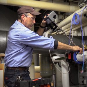
When purchasing a flowmeter for an HVAC application, such as boiler feed water monitoring or chilled/condenser water monitoring, we found that our customers value the ability to hot-tap (or pressure tap) a pipe to install an insertion flowmeter. This is done by installing an isolation valve in a pipe, allowing an insertion flowmeter to be placed into and removed from a live system without having to drain it. Draining a system is time consuming, costly, and generally not a good option for HVAC systems in buildings because it requires the entire system to be shut down. Permanently installing a hot-tap valve followed by an insertion flowmeter (with hot-tap capability) is an ideal alternative to a costly inline meter.
When considering an insertion flowmeter for an HVAC application, there are four key sources of error to be aware of:
- Wear of moving parts
- Pipe diameter variations
- Installation depth
- Fluid composition
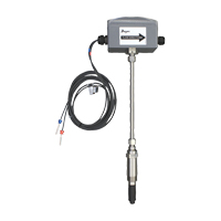
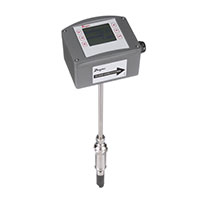
As the Dwyer team developed the Series IEF Insertion Electromagnetic Flow Transmitter and Series IEFB Insertion Thermal Energy Meter, we incorporated solutions to correct for each of these sources of error. The following paragraphs highlight how our unique magmeter design avoids or minimizes each source of error.
Source of Error: Wear of Moving Parts
The market standard for HVAC applications is a mechanical insertion flowmeter, which uses paddlewheel or turbine technology. The function of mechanical meters depends on the constant movement of a rotor, impeller, or turbine. Mechanical technology is very cost effective, but is highly susceptible to wear. After some use, the bearings holding the shaft may shift, affecting the shaft and causing the mechanical component to loosen. A shifted bearing or loose mechanical component can cause inconsistency in the flow readings, potential damage to the turbine, or damage to the entire flowmeter.
IEF/IEFB Solution
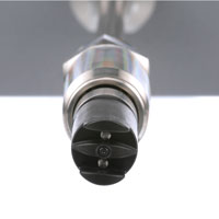 The obvious solution to prevent the wear of moving parts is to use non-moving part technology, which is why we specifically chose to use electromagnetic technology when developing the IEF and IEFB. The IEF and IEFB measurement technology consists of a probe and two sensors. By eliminating moving parts, this guarantees a longer life cycle, minimal maintenance, and performance that remains unchanged over time.
Source of Error: Pipe Diameter Variations
Two factors of internal pipe diameter can cause errors in flow measurement:
- Nominal pipe size (the external diameter)
- Pipe wall tolerance
Flow is a function of velocity and the cross section area, which varies depending on the pipe. The cross sectional area of the pipe is a function of the inside diameter, which includes the tolerance on the pipe wall thickness. Both the inside diameter and tolerance on the pipe wall thickness can stack up to equate to a significant difference in reading, particularly on smaller pipe sizes.
IEF/IEFB Solution
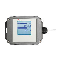
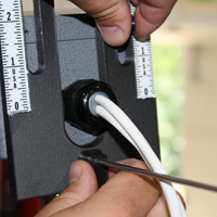
A good solution for accommodating these pipe diameter variations is to measure the actual dimensions of your application pipe. Measure the circumference of your pipe with a measuring tape and measure actual pipe wall thickness with an ultrasonic thickness gauge. This information can then be input into a field-configurable display. Based on your measurements, the IEF and IEFB will compute the actual pipe inside diameter to yield the most accurate flow reading.
Source of Error: Installation Depth
When it comes to insertion flowmeters, installation depth is essential to the accuracy of the flow measurement. In particular, the sensor needs to be placed at the calibrated velocity point in order to read the flow at the stated accuracy.
IEF/IEFB Solution
The IEF and IEFB come standard with an easy-to-use alignment tool to ensure that the meter is installed at the correct depth and that the sensor is aligned correctly with the flow.
Source of Error: Fluid Compensation
Glycol is often added to water in cooling systems to lower the freezing point. Typical glycol concentrations in these cooling systems are 25% to 50%. Variance in viscosity and density affects the flow profile around insertion flow meters, potentially causing errors in the reading. Errors are greatest at low velocities and also change with temperature.
IEF/IEFB Solution
The IEF and IEFB compensate for changes in viscosity and density in water-glycol mixtures over temperature and velocity. You can input the glycol percentage into the integral or remote LCD display and the IEF and IEFB will accurately compensate for changes in the viscosity and density. In addition, there is a temperature sensor in the probe that will compensate for changes in the fluid temperature.
The Series IEF and IEFB were designed to overcome the challenges faced by other HVAC flowmeters. If you are interested in learning about flow technologies more broadly, we have two other blog posts that go in detail regarding flow measurement technologies and the key differences between mechanical and non-mechanical flowmeters.
For any questions about using the IEF or IEFB, the Dwyer Applications Engineers are available to assist by phone at (219) 879-8000 x6402, or by email at tech@dwyermail.com.