 Have you ever been in an office, classroom, or hospital room where you change the wall mount humidity/temperature sensors that are integrated into a building automation system (BAS) and felt little to no change in the space? Worse yet, have you ever seen two sensors side by side reading different humidity values? Humidity and temperature sensors are manufactured by numerous companies and many of the occupants adjusting the settings or monitoring the current levels feel that the sensors are unreliable or have a poor accuracy.
Most of the units used in building automation systems are multi-variable instruments and often combine many sensors into a single housing to improve building aesthetics and limit the number of sensors in a single zone or space. These multi-variable instruments may include temperature, humidity, and carbon dioxide (CO2) sensing elements not to mention LCD or LED displays for local indication of measurements. With the addition of multiple sensors to minimize the number of sensors on the wall, the internal temperature of the sensor housing increases due to additional heat created from the additional sensors, such as the carbon dioxide sensor.
Since relative humidity is the ratio of the partial pressure of water in the air divided by the saturation pressure of water in the air (of which the latter is a function of temperature), relative humidity is inversely proportional to the local temperature. This means that as the temperature inside of the wall mount housing increases relative to the room temperature, the internal humidity sensor will read lower values compared to the actual room humidity.
To make matters worse, most manufacturers test and calibrate humidity sensors in a test chamber that has circulating airflow which helps to dissipate heat from the housing of the multi-variable instrument. Many applications such as classrooms, conference rooms, or hospital rooms are known to have stagnant air flow, meaning that there is no air flow through the sensor housing to dissipate the heat generated from displays, temperature sensors, or carbon dioxide sensing elements. This leads to the appearance of a lower than actual humidity reading in applications with stagnant air.
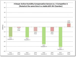
To counteract the increase in internal temperature of the humidity sensor, due to additional sensors and displays, Dwyer Instruments, Inc. developed a solution that provides a more accurate humidity reading in stagnant air applications.
The Dwyer Instruments, Inc. Solution
A separate temperature sensor is mounted on the outside of the wall mount housing and thermally isolated from the internal housing wall.
The internal humidity temperature sensor inside the housing is carefully calibrated to the outside temperature sensor so that minor variations in temperature between the inside and the outside of the housing can be determined. The saturation pressure of water is a well-known, complex function of only temperature. The humidity and temperature inside the wall mount housing is measured, and is always higher than the temperature outside of the housing. The difference between these two temperatures is used to compensate the humidity so that it indicates an accurate humidity measurement for the stagnant air space. This proprietary principle is Dwyer’s Digital Intelligent Temperature Compensation Algorithm (DITCA™) and can be found in Dwyer’s multi-variable lines of instruments.
Through the integration or our DITCA™ algorithm, our multi-variable sensors provide the aesthetics that you want and the accuracy that you need in one of the most common environments in a building automation system.